 "LIGHT ALARM"
Part 2
| Transistor Tester | Light Alarm | Blinker | Ticking Bomb | Signal Injector |
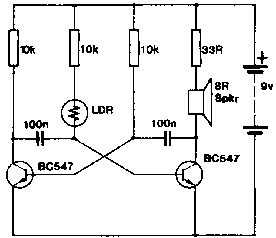
This project has a number of uses. Essentially it is a light alarm that is triggered into oscillation by a Light-Dependent-Resistor. Under dark conditions the LDR has a very high resistance and thus the second transistor has no bias on its base. This prevents the multivibrator from functioning and in this condition it draws only about 1mA. As the light intensity increases, the resistance of the photocell decreases and the multivibrator starts up.
Its frequency gradually rises to a high pitched whistle and is limited by the 10k limiting resistor in series with it.
Now, the possibilities for an alarm like this are endless. It will give an audible indication of the intensity of a light source or compare two illuminations. As an alarm it is useful as a theft indicator. It can be put into a cupboard or drawer to protect it from prying fingers. It can used as an alarm for the medicine chest or money drawer. In any case its advantage lies in the fact that it doesn't have to be wired to any switches and can be easily moved around.
 "LIGHT ALARM"
Circuit activated when light falls on Light dependent resistor.
A piece of veroboard 12 holes long will accommodate all the parts making it a very compact project which can be disguised as a packet of pills by using a suitable empty container.
Parts
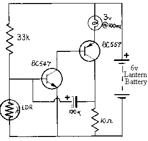
Have you seen the blinking lights at the road-side to warn motorists of roadworks or an excavation? These begin to operate only at dusk. They contain 2 lantern batteries, a Light-Dependent-Resistor and a 2-transistor flasher. The main requirement for a circuit to operate this type of warning device (apart from creating the flashes) is for its daytime current to be as low as possible to conserve the battery. Since the flash of the globe is extremely short, the average current drawn from the battery will be quite small. This circuit achieves both of these requirements.
 BLINKER
The stand-by current is only 100 microamp and the average operating current is less than 25 milliamps. The only two critical components in the circuit are the 10 ohm resistor and globe. The resistor must be 10 ohms. A 5 ohm or 15 ohm resistor will not work. The lamp must be a low current type. A miniature model railway globe o about 3v - 4v is ideal. It must be rated at .05 to .1 amp to operate successfully. Ordinary torch globes of 2.5v @ 300ma will not work at all. Use a light dependent resistor type ORP12 or similar which has a dark resistance of 10M and a light resistance of 300 ohms.
Parts
| Transistor Tester | Light Alarm | Blinker | Ticking Bomb | Signal Injector |
This article was taken from Talking Electronics